



How to design a circuit with cl21 - film capacitor?
 Nov 25, 2025|
 Hey there! As a supplier of CL21-film capacitors, I'm stoked to share with you how to design a circuit using these awesome components. CL21-film capacitors are super popular in the electronics world, and for good reason. They offer great performance, reliability, and are cost-effective. So, let's dive right in!
Understanding CL21-Film Capacitors
First things first, let's get to know what CL21-film capacitors are all about. These capacitors are made with a metalized polyester film as the dielectric material. This gives them some really cool properties. They have a high capacitance value for their size, which means you can pack a lot of capacitance into a small space. They also have low losses, which is great for efficiency in your circuit.
The CL21-film capacitors come in different voltage ratings, like CL21-Film Capacitor 100V and CL21-Film Capacitor 400V. You need to choose the right voltage rating based on the requirements of your circuit. If you use a capacitor with a voltage rating that's too low, it might break down and cause your circuit to fail. On the other hand, using a capacitor with a much higher voltage rating than necessary can be overkill and might cost you more.
Step 1: Define Your Circuit Requirements
The very first step in designing a circuit with CL21-film capacitors is to figure out what your circuit needs. What's the purpose of the circuit? Is it for filtering, coupling, or something else? You also need to know the frequency range of your circuit. Different applications have different frequency requirements, and the capacitance value of the capacitor you choose will depend on this.
For example, if you're designing a low-pass filter, you'll need to select a capacitor with a capacitance value that will allow low-frequency signals to pass through while blocking high-frequency signals. You can use some basic formulas to calculate the required capacitance value based on the cutoff frequency of your filter.
Step 2: Select the Right Capacitance Value
Once you know your circuit requirements, it's time to pick the right capacitance value for your CL21-film capacitor. Capacitance is measured in farads (F), but in most practical circuits, you'll be dealing with microfarads (μF) or picofarads (pF).

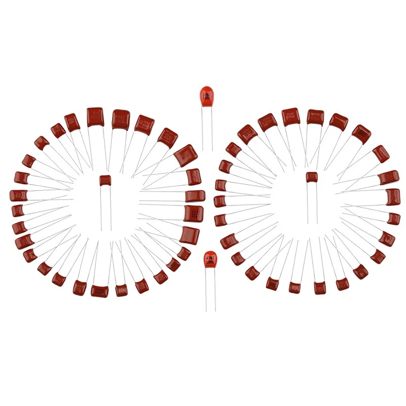
Let's say you're working on a coupling circuit. You want to pass an AC signal from one stage of your circuit to another while blocking the DC component. The capacitance value you choose will affect the frequency response of the coupling. A larger capacitance value will allow lower-frequency signals to pass more easily, while a smaller value will cut off lower frequencies.
If you need a 1μF capacitance for your circuit, you can check out our 1uf Polyester Capacitor. It's a great option for many applications.
Step 3: Consider the Voltage Rating
As I mentioned earlier, the voltage rating of the capacitor is crucial. You need to make sure that the capacitor can handle the maximum voltage that will be applied across it in your circuit. If your circuit operates at a relatively low voltage, like 100V, then a CL21-Film Capacitor 100V would be a good choice. But if your circuit has a higher voltage, say 400V, you'll need to go for the CL21-Film Capacitor 400V.
It's also a good idea to add some safety margin. For example, if your circuit is supposed to operate at 200V, you might want to choose a capacitor with a voltage rating of 400V to be on the safe side. This will help prevent the capacitor from breaking down due to voltage spikes or other unexpected conditions.
Step 4: Placement in the Circuit
The placement of the CL21-film capacitor in your circuit is important. You want to place it as close as possible to the component it's interacting with. For example, if it's a decoupling capacitor, you should place it as close as you can to the power pins of the integrated circuit (IC). This helps reduce the inductance in the power supply path and improves the stability of the power supply to the IC.
When you're laying out your printed circuit board (PCB), make sure to keep the traces short and wide. This will minimize the resistance and inductance in the circuit, which is important for the performance of the capacitor.
Step 5: Testing and Optimization
After you've designed your circuit and assembled it, it's time to test it. You can use an oscilloscope to check the voltage and current waveforms in your circuit. Look for any signs of distortion or instability. If you notice any issues, you might need to adjust the capacitance value or the placement of the capacitor.
You can also use a network analyzer to measure the frequency response of your circuit. This will help you verify that your circuit is working as expected and that the CL21-film capacitor is performing its intended function.
Conclusion
Designing a circuit with CL21-film capacitors is a fun and rewarding process. By following these steps, you can ensure that you select the right capacitor for your circuit and place it correctly to achieve the best performance.
If you're interested in purchasing CL21-film capacitors for your next project, don't hesitate to get in touch. We're here to help you find the perfect capacitors for your needs. Whether you're a hobbyist working on a small project or a professional engineer designing a large-scale circuit, we've got you covered.
References
- Horowitz, P., & Hill, W. (1989). The Art of Electronics. Cambridge University Press.
- Sedra, A. S., & Smith, K. C. (2015). Microelectronic Circuits. Oxford University Press.