




How to install cbb21 - film capacitor in a PCB?
 Aug 28, 2025|
 Installing a CBB21 - film capacitor on a Printed Circuit Board (PCB) is a task that, when done correctly, can significantly enhance the performance and reliability of your electronic device. As a trusted CBB21 - film capacitor supplier, I am here to guide you through the entire installation process, from understanding the capacitor to the actual soldering on the PCB.
Understanding the CBB21 - Film Capacitor
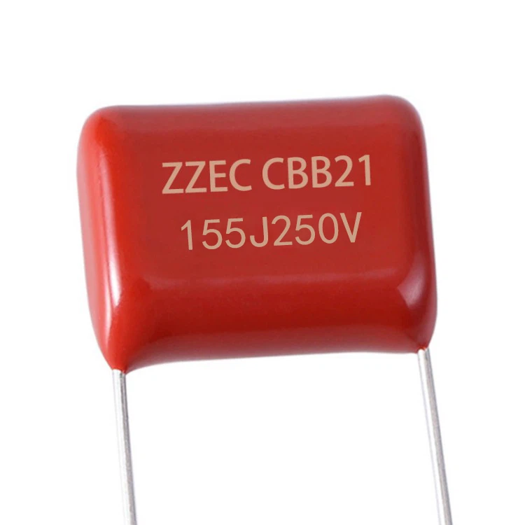
Before diving into the installation process, it's crucial to understand what a CBB21 - film capacitor is. The CBB21 - film capacitor is a type of metalized polypropylene film capacitor. It offers excellent electrical characteristics, such as low dielectric loss, high insulation resistance, and good self - healing properties. These features make it suitable for a wide range of applications, including filtering, coupling, and bypassing in electronic circuits.
There are various specifications of CBB21 - film capacitors available in the market. For instance, the CBB21 - Film Capacitor 250V is designed to handle a maximum voltage of 250 volts. Another common specification is the 104j 400v Capacitor, where "104" represents the capacitance value (10 x 10^4 pF or 0.1 μF) and "400v" indicates the rated voltage. Similarly, the 335j 400v Capacitor has a capacitance of 3.3 μF and a rated voltage of 400 volts.
Pre - installation Preparations
Selecting the Right Capacitor
The first step in the installation process is to select the appropriate CBB21 - film capacitor for your PCB. Consider the following factors:
- Capacitance Value: This is determined by the requirements of your circuit. Different circuits may need different capacitance values to function properly. For example, a filtering circuit may require a specific capacitance to remove unwanted frequencies.
- Voltage Rating: Ensure that the voltage rating of the capacitor is higher than the maximum voltage that will be applied across it in the circuit. Using a capacitor with a lower voltage rating can lead to capacitor failure and potentially damage the entire circuit.
- Tolerance: The tolerance of a capacitor indicates the allowable deviation from its nominal capacitance value. A lower tolerance means a more accurate capacitance, which may be necessary for precision circuits.
Gathering the Necessary Tools
To install the CBB21 - film capacitor on the PCB, you will need the following tools:
- Soldering Iron: A good quality soldering iron with adjustable temperature is essential. The temperature should be set according to the type of solder and the components being soldered.
- Solder: Choose a lead - free solder with a suitable melting point. The diameter of the solder wire depends on the size of the components and the soldering joints.
- Desoldering Pump or Braid: In case you make a mistake during soldering, a desoldering pump or braid can be used to remove the excess solder.
- Tweezers: Tweezers are useful for handling small components like the CBB21 - film capacitor and placing them accurately on the PCB.
- Multimeter: A multimeter can be used to measure the capacitance and voltage of the capacitor before and after installation to ensure its proper functioning.
Inspecting the PCB and Capacitor
Before installation, carefully inspect the PCB and the CBB21 - film capacitor. Check the PCB for any damaged or misaligned pads, and ensure that the holes for the capacitor leads are clean and free of debris. Inspect the capacitor for any visible damage, such as cracks or bent leads.
Installation Process
Placing the Capacitor on the PCB
- Identify the Pads: Locate the appropriate pads on the PCB where the CBB21 - film capacitor will be installed. These pads are usually marked with the component symbol or value.
- Insert the Leads: Use tweezers to pick up the capacitor and insert its leads into the corresponding holes on the PCB. Make sure the capacitor is placed in the correct orientation. In most cases, the capacitor is non - polarized, but it's still important to follow the circuit design.
- Secure the Capacitor: Once the leads are inserted, gently bend them slightly to hold the capacitor in place on the PCB. This will prevent it from falling out during the soldering process.
Soldering the Capacitor
- Pre - heat the Soldering Iron: Set the soldering iron to the appropriate temperature and allow it to heat up. The ideal temperature for soldering small electronic components like CBB21 - film capacitors is usually between 350°C and 400°C.
- Apply Solder to the Pad: Touch the tip of the soldering iron to the pad on the PCB for a few seconds to heat it up. Then, apply a small amount of solder to the pad. The solder should flow smoothly and cover the pad evenly.
- Solder the Capacitor Lead: Place the tip of the soldering iron on the lead of the capacitor where it meets the pad. Apply a small amount of solder to the joint. The solder should flow around the lead and form a smooth, shiny connection. Avoid using too much solder, as it can cause short circuits.
- Repeat for the Other Lead: Repeat the soldering process for the other lead of the capacitor. Make sure both joints are properly soldered and there are no cold solder joints (joints that are not fully melted or have a dull appearance).
Inspecting the Soldered Joints
After soldering, carefully inspect the soldered joints. Look for any signs of short circuits, such as solder bridges between adjacent pads. Check that the solder joints are smooth, shiny, and firmly attached to the leads and pads. If you find any issues, use a desoldering pump or braid to remove the excess solder and re - solder the joint.
Post - installation Checks
Measuring the Capacitance
Use a multimeter to measure the capacitance of the installed CBB21 - film capacitor. Compare the measured value with the nominal capacitance value to ensure that it is within the specified tolerance. If the measured value is significantly different, there may be a problem with the installation or the capacitor itself.
Testing the Circuit
Once the capacitor is installed and the soldering joints are inspected, power on the circuit and test its functionality. Check if the circuit is operating as expected and if there are any abnormal behaviors, such as overheating or incorrect output.
Troubleshooting
Cold Solder Joints
Cold solder joints can occur if the soldering iron temperature is too low or if the solder does not flow properly. To fix a cold solder joint, re - heat the joint with the soldering iron and add a small amount of additional solder. Make sure the solder flows smoothly and forms a good connection.
Short Circuits
Short circuits can be caused by excess solder bridging between adjacent pads or leads. Use a desoldering pump or braid to remove the excess solder and isolate the short circuit. Check the PCB for any damaged traces or pads that may be causing the short circuit.
Capacitor Failure
If the capacitor fails to function properly after installation, it may be due to a defective capacitor or incorrect installation. Replace the capacitor with a new one and ensure that the installation process is carried out correctly.
Conclusion
Installing a CBB21 - film capacitor on a PCB is a relatively straightforward process if you follow the proper steps. By understanding the capacitor specifications, preparing the necessary tools, and following the installation and testing procedures, you can ensure a successful installation. As a CBB21 - film capacitor supplier, we offer a wide range of high - quality capacitors to meet your various circuit requirements. If you have any questions or need assistance in selecting the right capacitor for your project, or if you are interested in purchasing our CBB21 - film capacitors, please feel free to contact us for further discussion and procurement negotiation.

References
- "Electronic Components and Circuit Theory" by Robert L. Boylestad and Louis Nashelsky
- "Practical Electronics for Inventors" by Paul Scherz and Simon Monk